|
Dla tego produktu nie napisano jeszcze recenzji!
 ;
Schematy są ale można wysilić się i zrobić kolorowy skan i o większej rozdzielczości. Wtedy schematy płytek będą czytelniejsze. Całość super jako wartość merytoryczna. Wszystkie dane potrzebne do podłączenia różnego rodzajów urządzeń takich gramofon, CD itd.
 ;
Szybko, sprawnie i tanio. Serwis godny polecenia. Będę polecał innym
;
Ogólnie jest OK, z wyjątkiem obrazu płyty głównej, który jest miejscami mało czytelny, ale można sobie poradzić.
;
Dokładna dokumentacja, pomogła w szybkiej naprawie telewizora. Dziękuję!
;
jedyne do czego mogę mieć zastrzeżenie to jakość zdjęć zawartych w przesłanej instrukcji serwisowej ponieważ są fatalnej jakości, praktycznie nieczytelne. tak poza tym jestem zadowolony to jest to czego szukałem.
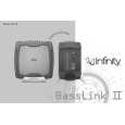
Powered Subwoofer
Basslink II
BASSLINK II DISASSEMBLY
1) Remove �Amplifier Dock� cover; (8) Phillips screws. 2) Remove (10) Phillips screws holding main heatsink/amplifier to enclosure, tapping the heatsink with a rubber mallet may be necessary to loosen it. Pull amplifier from enclosure 3) Remove single 12 pin Molex connector M300 and both pairs of FASTON terminals from the amplifier PCB; do not mix up the two pairs of red/black wires (speaker and A/B). Label if necessary. 4) With the screw cavities facing upwards on the enclosure, remove the (12) Phillips screws holding the enclosure together. 5) Using the opening of the �Amplifier Dock� as leverage, separate the enclosure halves; to completely separate the wiring, remove the 8 pin Molex connector M200 from the Jack/Limiter PCB. 6) If the Gain PCB (Gain/Xover/Base pots) needs to be accessed, there is an additional screw holding the plastic cover on, besides the two exposed ones, that must be removed and is visible after removing the 10" passive radiator (8 Phillips screws) 7) The Jack PCB is not serviceable, as it is attached to the enclosure with adhesive. 8) Reassembly: follow in reverse order, and be sure to not mix the red/black wire pair (speaker and A/B) on the MAIN PCB when you connect them to the FASTON terminals.
9
|